
Another day, another random display from WaveShare that has pretty poor documentation, and me trying to get it working with CircuitPython… I must be CRAZY
NB: As always, I waffle on a bit here… click here to skip to the tl;dr technical details

Quick back story here, a friend of my was using one of these WaveShare screens, so I thought I would grab one and have a look at it. Found them on amazon for about £20…. now if you have read my previous post about getting the smaller 1.47″ screen working, you know that it takes a bit of changing to get things working.
For that device, I had designed and built a custom PCB that handled the power, had a place for a pico, used SPI to control a screen, and also had pins to attach an SD card reader over SPI… after multiple board designs and a lot of hair pulling I have something that works. So to find this thing that does the same thing, in a neat package with a bigger screen with touch screen… was you know… annoying. But ho-hum, lets give it a go.
The device
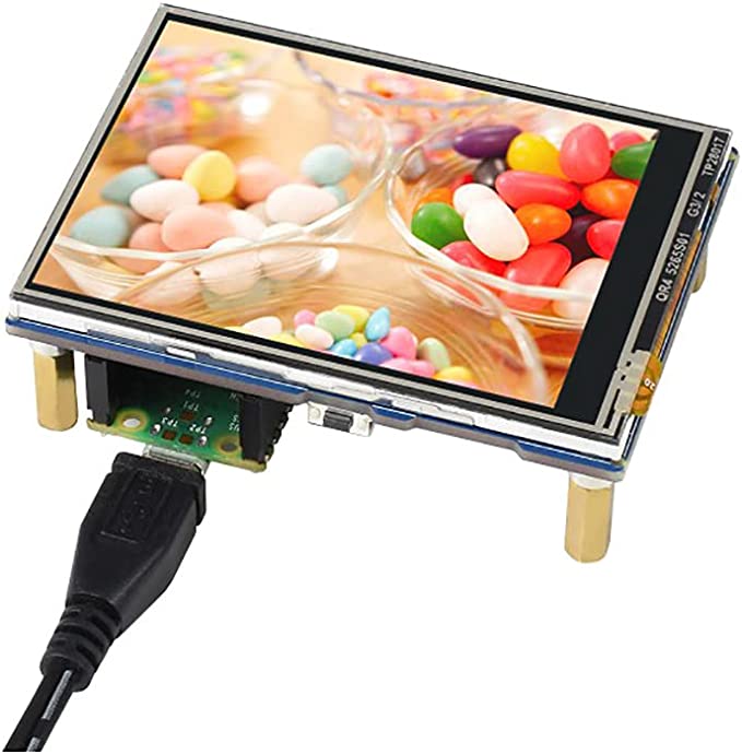

The device itself is a nice bit of kit, my only criticism is that there’s not much option for breaking out other pins to do anything else with… I got around this by using some right angle headers that expose a little bit of header out to the side that mean I can solder a bit of wire on…. like this

Their documentation isnt great (as is the norm with waveshare) .. different download links can give you slightly different demo files… one called Pico-ResTouch-LCD-X_X_Code_(6).zip and another just Pico-ResTouch-LCD-X_X_Code.zip as with the other display, these are C and full python, with little to no explanation so not much use for me, using CircuitPython.
Anyway… recycling my older code, I found some SD card SPI code, and I plugged that in, followed their pinout from the website and found that it worked…. so the SPI was hooked up correctly. Now this also runs off a ST7789 just like the small display, so in theory, my old code should work ok, based off the adafruit driver on github.
So I changed the pins, and used my old display code for the display… nothing, no life…. no errors, but no life.
After trawling through their source code I found this snippet:
SSD = ST7789
pdc = Pin(8, Pin.OUT, value=0)
pcs = Pin(9, Pin.OUT, value=1)
prst = Pin(15, Pin.OUT, value=1)
pbl = Pin(13, Pin.OUT, value=1)
Now, the small display didn’t seem to make use of the bl pin, with my usage, I think I had it hooked up wrong maybe to the Pico’s SPI MOSI or something… but as its a display, it never outputs anything so it worked. However, this display seemed to be causing me an issue copying my old code, but that one line where they say pbl = Pin(13, Pin.OUT, value=1) looks to me like they are setting pin 13 high and doing something with a backlight… so back to my CircuitPython code, and declare that pin as an output and set it to True… bob’s your uncle. We have life!

The Code
import board
import busio
import terminalio
import displayio
import time
import digitalio

import os
import sdcardio
import storage
import sys

from adafruit_display_text import label
from adafruit_st7789 import ST7789

# ON BOARD LED
led = digitalio.DigitalInOut(board.LED)
led.direction = digitalio.Direction.OUTPUT

# Release any resources currently in use for the displays
displayio.release_displays()

tft_dc = board.GP8
tft_cs = board.GP9
tft_rst = board.GP15

tft_bl = digitalio.DigitalInOut(board.GP13)
tft_bl.direction = digitalio.Direction.OUTPUT
tft_bl.value = True

# Clock, MOSI, MISO
spi = busio.SPI(board.GP10, board.GP11, board.GP12)
print(str(spi.frequency))

display_bus = displayio.FourWire(spi, command=tft_dc, chip_select=tft_cs, reset=tft_rst)
display = ST7789(display_bus, width=320, height=240, rotation=90)

# Make the display context
splash = displayio.Group()
display.show(splash)

color_bitmap = displayio.Bitmap(320, 240, 1)
color_palette = displayio.Palette(1)
color_palette[0] = 0x00FF00  # Bright Green

bg_sprite = displayio.TileGrid(color_bitmap, pixel_shader=color_palette, x=0, y=0)
splash.append(bg_sprite)

# Draw a smaller inner rectangle
inner_bitmap = displayio.Bitmap(280, 200, 1)
inner_palette = displayio.Palette(1)
inner_palette[0] = 0xAA0088  # Purple
inner_sprite = displayio.TileGrid(inner_bitmap, pixel_shader=inner_palette, x=20, y=20)
splash.append(inner_sprite)

# Draw a label
text_group = displayio.Group(scale=3, x=57, y=120)
text = "Hello World!"
text_area = label.Label(terminalio.FONT, text=text, color=0xFFFF00)
text_group.append(text_area)  # Subgroup for text scaling
splash.append(text_group)

count = 0
last_print = time.monotonic()
while True:
    current = time.monotonic()

    if current - last_print >= 1.0:
        last_print = current

        #print("Loop " + str(count))
        count = count + 1

        if led.value == True:
            led.value = False
        else:
            led.value = True
As before, you will need to drop in a few CirctuitPython libraries from their bundle, namely:
adafruit_display_text
adafruit_st7789.mpy
But that should get you up and running…
Oh and that red case is one I found here on printables …. I printed a face plate that pressure fits inside, and can mount this pico display on, with a hole for a USB cable for power/debugging and a bit of proto-board to attach whatever I want, like buttons or the L80-M39 GPS module I like working with to to expand the project and keep it in a box!
If this helps, please leave a comment or hit me up on twitter or mastadon (@markmcgookin@qoto.org).
Happy Hacking.

Hey there, did you manage to get the XPT2046 Touchinput working under Circuitpython ?
LikeLike
Hey there, did you mange to get XPT2046-Touchinput working under Circuitpython as well ?
LikeLiked by 1 person
Hi, no I looked into it, but I never got it working. Let me know if you do though!
LikeLike
got now tft working, or touch working, but not both at the same time.
more important, i found this:
https://github.com/demc/waveshare-pico-restouch-circuitpython
(hadn’t the time to try it out yet)
LikeLiked by 1 person
Ah nice one! For my build I think I am using the touch pins for other things now, so it wouldn’t work for me, but great if you want to use it like that in the future!
LikeLike
Hi there. I’m writing to let you know that the recent update of displayio seems to have deprecated the display.show() method and instead requires the use of the display.root_group property.
(changes)
display.show(splash)
(New)
display.root_group = splash
LikeLike
Hi there. I’m writing to let you know that the recent update of displayio seems to have deprecated the display.show() method and instead requires the use of the display.root_group property.
(changes)
display.show(splash)
(New)
display.root_group = splash
LikeLike
Ah great, thanks for the update!
LikeLike
Hi there. I’m writing to let you know that the recent update of displayio seems to have deprecated the display.show() method and instead requires the use of the display.root_group property.
(changes)
display.show(splash)
(New)
display.root_group = splash
LikeLike