
I recently purchased (read: impulse bought) two of these Waveshare 1.47″ SPI Displays, with curved corners. Looks pretty great, and I thought it might be interesting to use in a project that I am working on using a Raspberry Pi Pico W, they have a picture of it wired up to a pico on the site, so great stuff.
Not so easy, digging through the waveshare site is a bit of a chore, but you can eventually find their product Wiki here and after a few attempts and failed downloads, you can grab zip file with some example code in it…
This is where things get frustrating… they have python code, but aimed at running on a Raspberry Pi where you can run apt-get commands etc. or some C++ code to run on Arduino. I already wanted to run CircuitPython or MicroPython on my pico, as the support for Neopixels (another part of this project) is a lot better in my mind, and I just don’t like C++ that much.
I committed to CircuitPython, and started digging through the Adafruit GitHub for some inspiration… I read the datasheet for the screen and saw that it had a ST7789V3 control chip, and found Adafruits ST7789 repository in there I found an example for a 1.47″ Screen!

Progress!
Alas, it didn’t work….. the top of the example code from here, looks like this:
import board
import terminalio
import displayio
from adafruit_display_text import label
from adafruit_st7789 import ST7789

BORDER_WIDTH = 20
TEXT_SCALE = 3

# Release any resources currently in use for the displays
displayio.release_displays()

spi = board.SPI()
tft_cs = board.D5
tft_dc = board.D6
tft_rst = board.D9

display_bus = displayio.FourWire(spi, command=tft_dc, chip_select=tft_cs, reset=tft_rst)
But that barfs when trying to run it on the Pico…. so a few changes are required.
For starters, you will need to load circuitpython onto your pico… download the appropriate UF2 file (a beta version of v8 at the time of writing) and hold the button on your pico and plug it into your computer… it will show up as a usb drive. Copy the UF2 over, and it will restart and show up as a CircuitPython device, in which is a lib folder.
Then you will need to download the circuitpython bundle to grab some extra libraries. You will need to copy:
adafruit_display_text
adafruit_st7789.mpy
neopixel.mpy
over into the lib folder on your pico.
The only real changes to the code are in the first portion above… change it to this
import board
import busio
import terminalio
import displayio

from adafruit_display_text import label
from adafruit_st7789 import ST7789

BORDER_WIDTH = 28
TEXT_SCALE = 3

# Release any resources currently in use for the displays
displayio.release_displays()

tft_cs = board.GP5
tft_dc = board.GP6
tft_rst = board.GP7

spi = busio.SPI(board.GP2, board.GP3, board.GP4)
display_bus = displayio.FourWire(spi, command=tft_dc, chip_select=tft_cs, reset=tft_rst)
As you can see, there are a few minor changes (underlined). We are now using busio.SPI instead of board.SPI. This has a few arguments, namely your clock, MOSI and MOSO pins. Our pin references are different too.. instead of D6 etc we are now using GP6. I am not sure if this is the nature of it being on a pico, or the sample code is just out of date.
In my example here I am building the SPI connection from the Picos SPI0 using pins GP2,GP3 and GP4 (You can see this in the great pinout by Gadgetoid here) then further communication will be happening on GP5,GP6, and GP7.
The screen does come with a cable with some dupont connectors on one end, so you can just plug these in yourself using the variable names above as a guide. Mine looked like this:
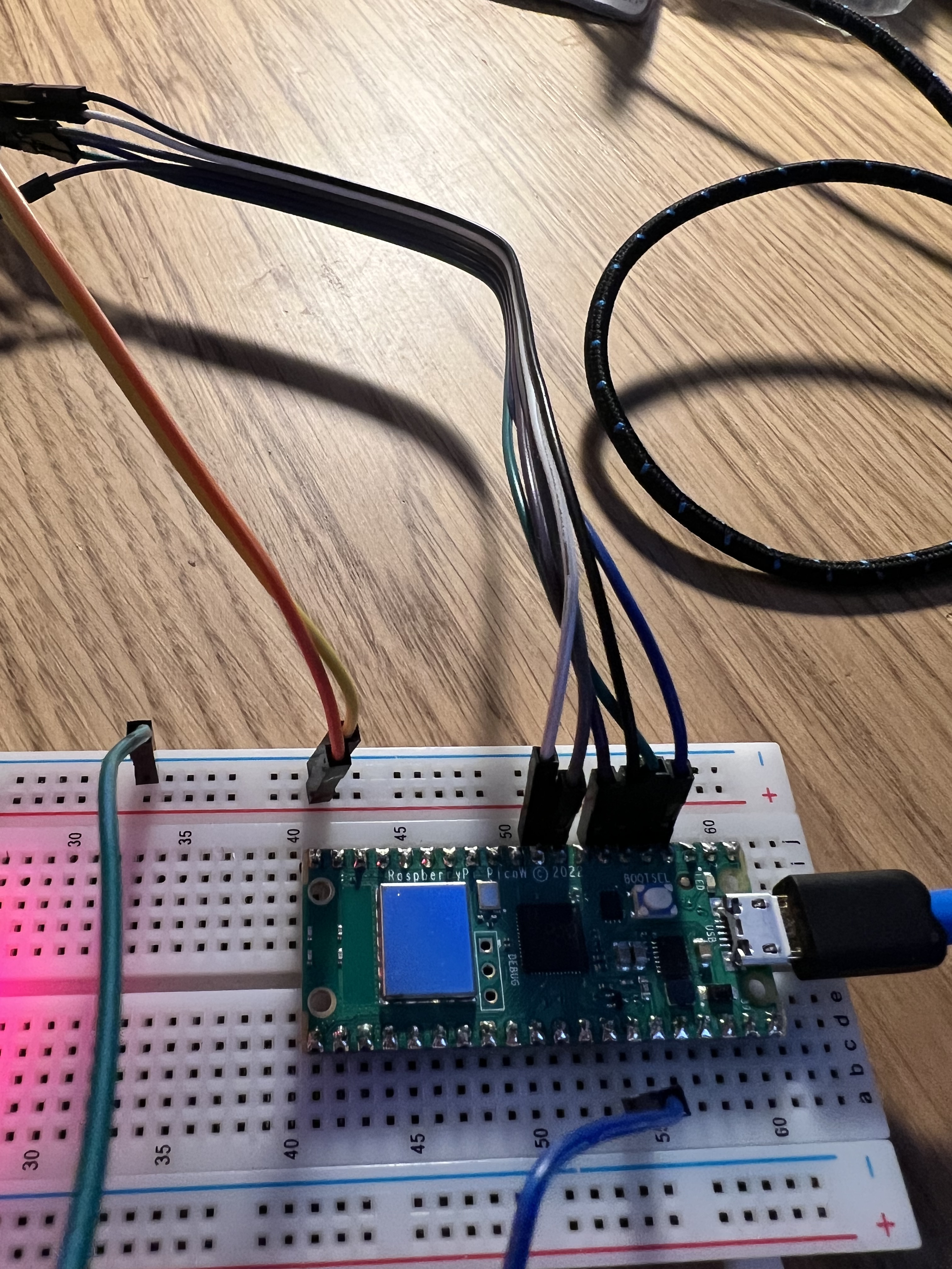
Mine works like this:
DISPLAY > BOARD
VCC - 3v3 Rail
GND - GND Rail
DIN - GP3
CLK - GP2
CS - GP5
DC - GP6
RST - GP7
BL - GP4
I must admit that took a bit of figuring out, but once I understood what was going on it was pretty simple. The MISO (Module in Sensor Out) and MOSI (Vice Versa) pins are the Tx (Transmit) and Rx (Receive) pins on the Pico. I stuck it all down on my PCB silk screen anyway so I don’t forget.

You can then power your pico via VSYS (3.3v) or via USB… up to you. I would recomment powering the display directly from a 3v3 rail and not the pico as when I drove mine from the Pico it was very dim.
Once you load the updated example code into place on your pico it will restart, and if you have everything connected ok, you should have a working 1.47″ screen.

And that’s about it. I haven’t delved into what the adafruit library is capable of just yet, but I have ordered a PCB with traces doing the wiring for the screen to make it a bit less of a cable tangle so I can just run 8 straight cables to the display.
Have fun hacking, and let me know if this was useful in the comments!

I’ve made the mistake as you and bought this display as it looked nice and then found out the documentation is poor and doesn’t cover the pi Pico. Thanks for the write-up!
LikeLiked by 1 person
Haha. Yeah that’s the curse of being a techy! Hope you find a use for it!
LikeLike
I took the easy way out after 3 nights of getting nowhere trying to modify other sample files whilst bashing my head against the desk… contacted the supplier to put me in touch with the manufacturer who responded pretty quickly with a sample code for micropython, ill paste their link below!
Zera (Waveshare)
Mar 25, 2023, 17:10 GMT+8
Yes, please check it:
The newest examples: https://www.waveshare.net/w/upload/f/fc/LCD_Module_code.zip
connection:
Module Pico
VCC 3.3V
GND GND
DIN GP11
CLK GP10
CS GP9
DC GP8
RST GP12
BL GP13
hope this is some help to you if its still an active project your meddling with!
LikeLiked by 1 person