
Inspiration
I have got about three Raspberry Pis knocking about my house, all in various states of incomplete projects. I love to play with them, and get things working, but I never seem to finish the projects as they always seem to involve a bit of extra tech/resources that I don’t have.
But recently I came across a blog entry by Frederick Vandenbosh where he used a Pi Zero to create a small, internet connected, display with two buttons and a range of functions. I decided that I would give it a try, and commit to building it, and extending it. I found his blog entry lacked a few steps for a basic user that can halt a project like this, so I have tried to provide a few bits of information that Frederick hasn’t mentioned.
So firstly, thanks to Frederick for the inspiration, you can check out his blog here for lots of cool Pi Projects.
Getting all the parts
For the case, Frederick’s project involved a 3D printed case, and while I would love a 3D printer, I don’t have one yet, and decided to improvise. I chose to take some Perspex and cut it into an acceptable shape, finish it off with a mix of hot glue and Sugru.
I am working using a Raspberry Pi 3 as a development machine, but will be porting the final product over to a Raspberry Pi Zero before adding it into the case.
I have had to do some soldering for the display and Pi Zero itself, nothing major and easily doable for even a beginner with a few youtube tutorials.
I have some parts from an Arduino starter kit (like a breadboard and buttons) that made life a bit easier.
Sugru
Raspberry Pi 3
Raspberry Pi Zero
Soldering Kit
Arduino Display
Arduino Kit
Setting up the Raspberry Pi
Check out this blog post for setting up your Raspberry Pi.
Soldering the display
I used the kit I mentioned above to solder the adafruit display to the pins that come with it, this means that I can use standard Male/Female wiring or a breadboard to control the device without soldering more and more bits together. I didn’t take any pictures while soldering, as that would have required more hands than evolution blessed me with. There is a good tutorial here on how to solder pins to a PCB. The guy is using an arduino, but it’s a similar size and pin setup.
If everything goes ok, you should end up with something like this. (Remember to put the short bits on the display side, or you will need to connect wires above the display and that will make it pretty hard to fit in a case.
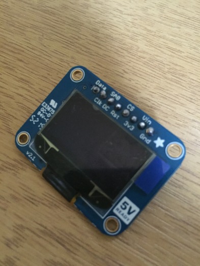
(Clearly I’m not an expert, but this is good enough for me!)
We will be wiring up the display and communicating with it using a protocol called “I2C” this is a setting that you need to enable on the pi itself. The best method is to use
sudo raspi-config
the process is described here in great detail. Take note of the two apt-get commands that you need to run to install the libraries required to communicate over I2C.
It is also important to note, that if you are using the Adafruit SSD1306 display like I am, there are two jumpers on the back of the display that you need to solder over to connect and enable I2C on the device (I was pulling my hair out before realising that I had to do this) it should look like this when complete.
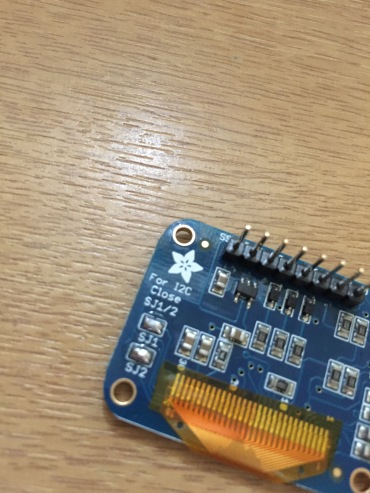
(Note the SJ1 and SJ2 jumpers that are connected)
That is your display ready to be used!
Connecting the display to the Pi
The wiring pattern is the I2C Pattern as mentioned before. This can be a little slower to respond than something like SPI but it uses less pins, so is suited for our fairly compact project.
The wiring is exactly as Frederick mentions in his blog and he provides a great diagram for hooking it up.
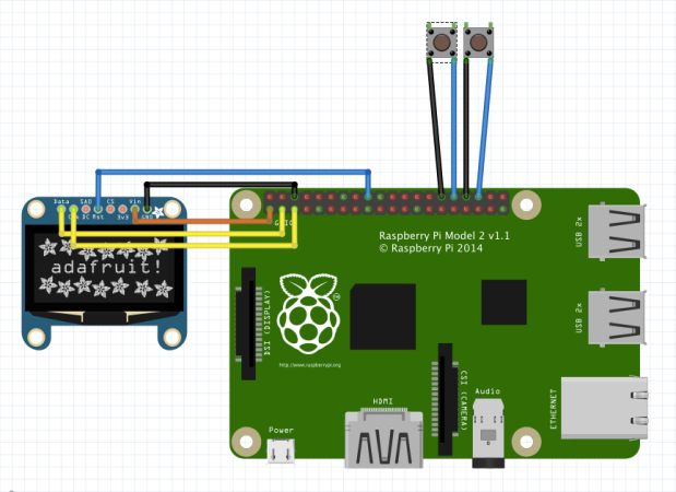
(The original image is from Frederick’s blog and can be found here)
If you have a breadboard like I have, you can use it to connect the display to the pi without any further soldering. Remember, breadboards connect horizontally so if you plug your display in Rows 1-8 in slot A you can use slot B (or any other) on those same rows to connect to the appropriate pins (As I have done below)
Preparing the software
Now you need to install some libraries on the Pi so that you can interact with the display, Frederick doesn’t mention that in his blog, but if you follow the steps here you should be up and running. You need to update the apt libraries, install some python and linux tools, install PIP (A python specific package manager), install a Python GPIO library and finally a python image library to allow you to construct images to output to the screen .In short:
sudo apt-get update
sudo apt-get install build-essential python-dev python-pip
sudo pip install RPi.GPIO
sudo apt-get install python-imaging python-smbus
Once that is complete, you need to get the Adafruit libraries for interacting with the display. They are all available on the Adafruit GitHub page. That is done as follows
sudo apt-get install git
git clone https://github.com/adafruit/Adafruit_Python_SSD1306.git
cd Adafruit_Python_SSD1306
sudo python setup.py install
This downloads the Adafruit python libraries for talking to the display, and installs/builds them so that they are easy to use.
Modifying the python files to work with the Pi
Now this is a step that took me a while to figure out, and I didn’t find it documented anywhere. Remote onto your Pi with SSH or Microsoft Remote Desktop (using XRDP) or simply connect it to a monitor, you need to run a command as follows (once the Pi is wired up correctly)
sudo i2cdetect -y l
You should get a grid output, telling you how your display is connected that looks something like this
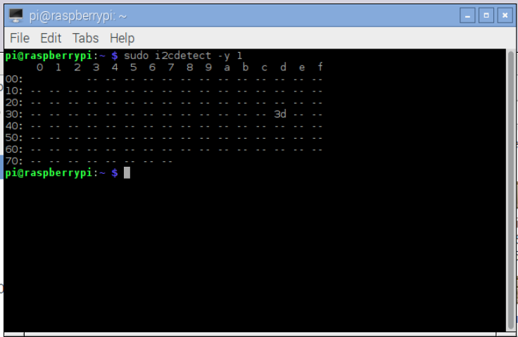
In the image above, you can see that 3d is shown. That means I am connected on address 0x3D this is important in a minute.
On the pi, navigate to the Adafruit git folder you downloaded. Mine was located in /home/pi/Adafruit_Python_SSD1306. In here, navigate to the “Adafruit_SSD1306” folder and you can see a file called “SSD1306.py”
One of the first lines in there you will see is
SSD1306_I2C_ADDRESS = 0x3C
and you need to change that to
SSD1306_I2C_ADDRESS = 0x3D
(Note the 3D that we spotted earlier)
That alone isn’t quite enough, as remember we ran an “Install” command a while ago? Well that was compiling this code, and it’s the compiled code that we are running when we reference the library. So we need to re-run the command
sudo python setup.py install
in the root of the Adafruit git folder. i.e. From inside the folder we downloaded with the git command earlier.
Fonts
Now, Frederick uses a font called “Minecraftia.ttf” in his blog post, and in the comments he mentions where it can be downloaded from. If you download the .zip file from here (on your pi using it’s web browser) http://www.dafont.com/minecraftia.font and extract it using package manager (right click on the pi, and extract here).
I tried a few approaches to installing this font and found that the best way was to copy it to a folder beside the code I am running and reference the file directly.
Time to code
Now, Frederick’s prototype has some great code for a little device like this, so I just took his python script exactly and followed his instructions on how to load it at run time (so it runs as soon as the Pi boots up) .. I am not going to try and improve it right now, my only change was to reference the font file in the folder below the script one, so every line like this:
font = ImageFont.truetype('Minecraftia.ttf', 35)
now looks like this
font = ImageFont.truetype('fonts/Minecraftia.ttf', 35)
Your best bet is to just take his script and save it onto your pi, and make that change if you are having issues with the fonts. Here is a link to the raw script.
Placement of this script is important, it needs to be able to see the Adafruit libraries and the font we mentioned. I copied the folders and files so my directory structure looks like this:
/home/pi/project/
    -- Adafruit_Python_SSD1306 (the git folder)
    --info_display.py (Frederick's program)
    --launcher.sh (Frederick's launcher script)
    --fonts (folder)
         --Minecraftia-Regular.ttf
You can also see Frederick’s blog for writing a launcher bash script and using a cron job to run it when the Pi boots (you don’t have to know what those things are, Frederick explains exactly how to use them to get the script to run on booting up the Pi)
Done!
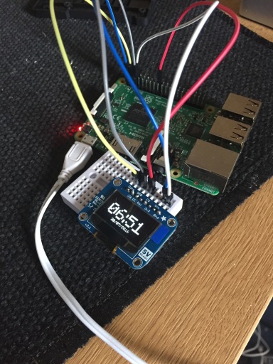
And that’s it! I copied Frederick’s diagram and added a few buttons to my breadboard to switch between modes, and it worked perfectly. You can also use the IDLE IDE on the Pi itself to run the code by opening the info_display.py file and selecting “Run Module” from the menu, or just reboot the Pi and watch it work. If you run into any errors, run the module through IDLE and it should report any problems.
Hope it all works out well, and thanks very much to Frederick for the blog, this is basically all his work with a few pointers from me!
I’ll post updates soon on constructing a case and migrating the project to a Pi Zero, then onto modifying it to run off batteries and adding new features!

Great post, glad my project inspired you! 🙂
LikeLike
Since you have multiple Pi’s, don’t forget that GPIO supports *remote* GPIO. So you can have your Pi3 send GPIO commands over the wi-fi to your Pi0 to talk to its pins if you want.
LikeLike